Hello everyone,
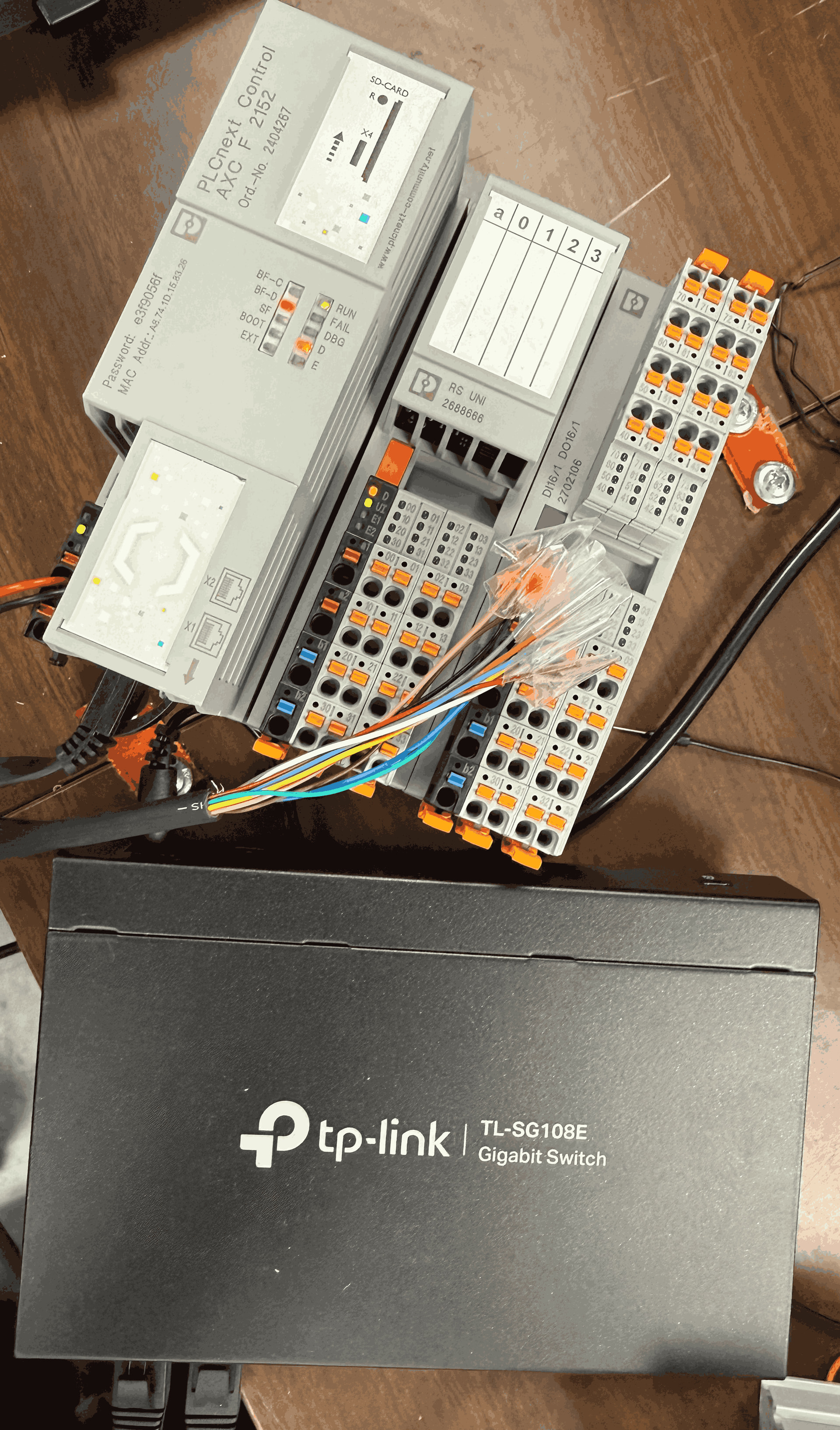
I am currently trying to connect a FLIR A70 thermal camera with a PLC (currently testing with Phoenix Contact PLCnext AXC F 2152, but information for any PLC is welcome).
Current setup:
-
FLIR A70 thermal camera
-
PLC connected through Ethernet switch
-
Laptop connected through the same Ethernet switch
-
Using the M8 ETH/PoE connector for Ethernet communication
-
Using the M12 PWR/DIG I/O cable with free colored wires connected toward the PLC
-
The M4 RS232/485 connector is also available
I am confused about the correct wiring and communication setup.
Questions:
-
Should I use only the M8 ETH/PoE connection for communication?
-
Should the M12 PWR/DIG I/O cable also be connected simultaneously with Ethernet?
-
Is the M4 RS232/485 connection required when Ethernet communication is already being used?
-
For PLC communication, is Modbus TCP or Ethernet/IP the recommended method?
-
Has anyone successfully connected a FLIR A70 with any PLC such as Siemens, Allen Bradley, Beckhoff, Omron, Mitsubishi, Codesys, or PLCnext?
-
What is the usual purpose of the M12 PWR/DIG I/O connection when Ethernet is already connected?
Right now the communication path is:
FLIR A70 → Ethernet switch → PLC + Laptop
I would really appreciate any wiring diagrams, example configurations, screenshots, or recommendations regarding whether the ETH/PoE, PWR/DIG I/O, and RS232/485 connections should all be used together or only selectively.
Thank you.